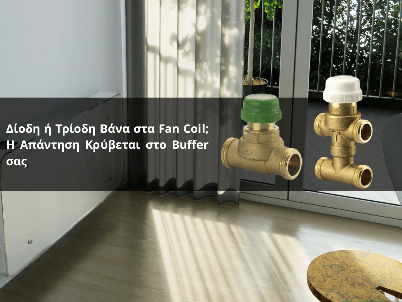
Whether to use a two-way or three-way valve on a fan coil unit is not a matter of preference, but of hydraulic design. Find out how each one works, what you gain from IVAR VFC valves (two-way and three-way) and a simple selection rule that depends on one thing: whether the system has a buffer tank or not.
Why does every fan coil unit need a valve?;
The fan coil unit provides heating or cooling only when the room requires it. The thermostat must be able to cut off the water supply to the unit once the desired temperature has been reached. Without a valve, water circulates continuously through the unit; the fan coil unit continues to operate via natural convection even when we do not want it to, and temperature control becomes inaccurate.
In a system with multiple fan coils, it is also the valve that allows for independent control in each room. The question, therefore, is not if We’ll fit a tap, but what sort of.
The role of Kv: why correct sizing is crucial for flow
The Kv (valve flow coefficient) indicates how much water flows through the valve for a given pressure drop. It is very easy to make the following mistake here: an undersized central zone solenoid valve «chokes» the entire zone, resulting in uneven distribution, noise and underperformance at the most remote outlets.
The solution is not a large central valve, but a correctly sized valve with a suitable Kv value on each fan coil unit. The selectable Kv rating of the IVAR VFC valves allows you to match the valve to the flow rate of each unit and achieve true hydraulic balancing, whilst for large fan coils, the high-flow VFC 02 (Kv up to 4.50) handles high flow rates without pressure drop. The valves can also be grouped on a manifold for centralised, accessible control.
Valve diodes (IVAR VFC 01 / VFC 02): cut off the flow
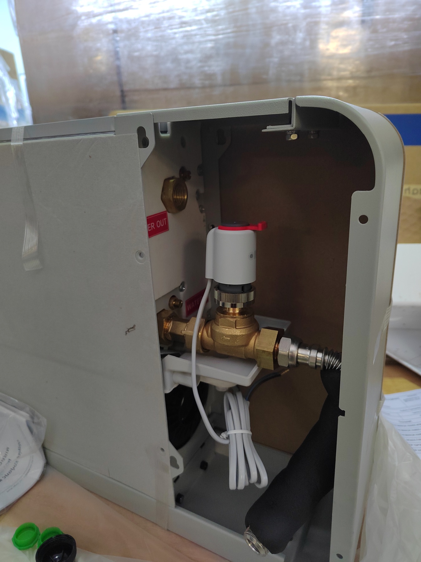
The diode is a two-way axial valve fitted to the return pipe of the fan coil, together with an electrothermal head. When a signal is received from the thermostat, completely cuts off the flow towards the element. The network operates with variable flow: The more fan coils that are switched off, the less water circulates.
It is simple, economical and has fewer connections.
What you need to bear in mind: If several diodes are switched off at the same time, the total power supply to the heat pump drops, and this is precisely where the buffer comes into play, as we shall see below.
IVAR data: The VFC 01 (G½” or G¾”) is available with a selectable Kv value ranging from 0.25 to 2.10, whilst the VFC 02, designed for high flow rates (high flow, G¾”) offers Kv values of 2.10 / 3.20 / 4.50. This allows you to select the correct Kv for the flow rate of each fan coil and balance the system.
Three-way valve (IVAR VFC 03): diverts the flow to the bypass
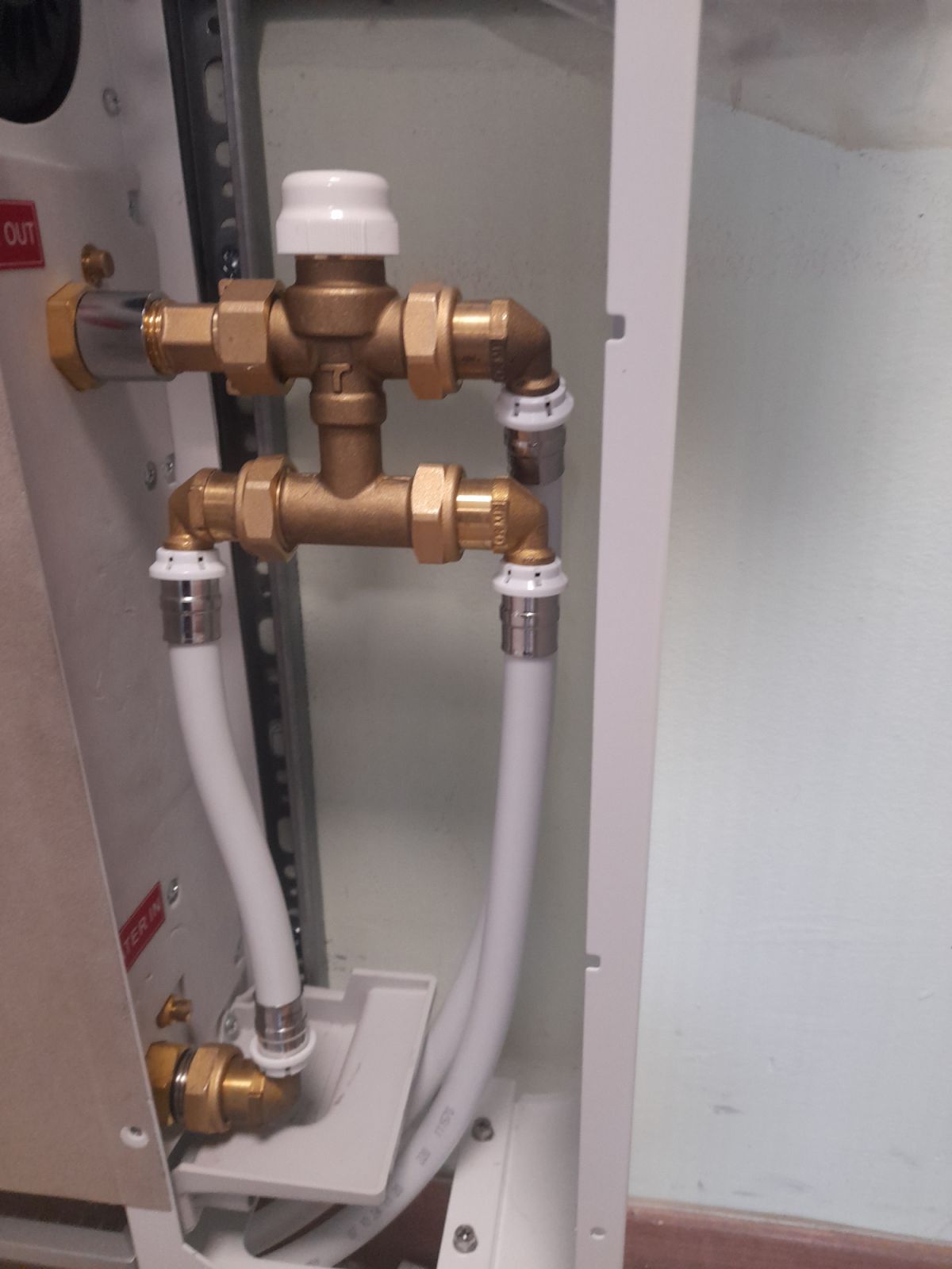
A three-way valve is a valve with 4 connections which can be fitted either before or after the fan coil. In response to a signal from the thermostat, the electrothermal actuator moves the piston and the valve operates in two modes: feeding ή by-pass.
The key point is this: once the room has reached the desired temperature, the water It does NOT pass through the element. It is diverted via a bypass except from the fan coil and is returned to the system. In this way, we achieve two things at once: the unit is isolated and cooled (correct control), whilst the flow in the primary circuit remains almost constant. This steady flow is the main advantage of the triode.
IVAR data: The VFC 03 (G½” or G¾”) is available with a Kv rating ranging from 0.25 to 2.50 and a piston stroke of 3 mm.
Both series share the same technical limits: maximum temperature 120 °C, maximum pressure 10 bar, maximum differential pressure with an electrothermal head fitted of 1.5 bar, and fluids ranging from water to 50%. They are driven by the same on/off electrothermal head with M30×1.5 thread the same model as the underfloor heads, so they can be sourced from the same stock and are easy to replace.
Please note: wall-mounted fan coils with a built-in room sensor
Many wall-mounted fan coils have a temperature sensor built into the machine (in the path of the intake air). If water continues to flow through the element whilst the fan has stopped, the hot/cold element affects the air around it, the sensor «reads» the element instead of the room, and naturally does not function correctly.
The point here is clear: once the room has reached the desired temperature, you must the flow of water through the element stops. Both valves can achieve this, but in different ways. The two-way valve does so by cutting off the flow, whilst the three-way valve diverts it via a bypass outside the valve body. What you must absolutely avoid is continuous water flow through the element (e.g. without a valve or with incorrect wiring). For this reason, in systems with a built-in sensor, a valve with an electrothermal head is not a luxury but a necessity.
The simple rule of thumb: it all comes down to the buffer
If you take just one thing away from this article, let it be this:
- Three-way valve (VFC 03). Use this in a system WITHOUT a buffer tank. The three-way valve bypass ensures the minimum flow required by the heat pump even when all zones are shut off, thereby protecting the compressor from frequent starts, without the need for a buffer tank.
- Diodes (VFC 01 / 02) It is preferable to use these when there is a buffer and a second inverter circulator. The buffer provides the necessary volume and hydraulic separation, the second inverter circulator manages the variable flow in the secondary circuit, and the check valve offers a simpler, more economical solution without continuous bypass circulation.
In a nutshell: The three-terminal device «generates» the minimum current on its own, whilst the diode «borrows» it from the buffer and the second circulator. For a more detailed look at when the buffer is applied, see our article
Diode vs Triode: a comparison at a glance
| Feature | Diodes — VFC 01 / 02 | Trio — VFC 03 |
|---|---|---|
| Function | It cuts off the flow to the component (on/off) | Diverts the flow to a bypass, bypassing the element |
| Network flow | Variable | Virtually constant (ensures a minimum flow) |
| Links | 2 (on the return line) | 4 (before or after the fan coil) |
| Kv range (IVAR) | 0.25–2.10 · up to 4.50 (VFC 02 high-flow) | 0,25–2,50 |
| Ideal use | With a buffer + a second inverter circulator | No buffer — to ensure a minimum flow rate |
| General | COMMON CHARACTERISTICS M30×1.5 on/off electrothermal head · 120 °C · 10 bar · max. Δp 1.5 bar |
|
Practical points to bear in mind during installation
Select the Kv based on the nominal flow rate of each fan coil, not «approximately» — for large units, use the high-flow VFC 02. Observe the maximum differential pressure of 1.5 bar at the head; in systems with high manometric pressure, provide a differential pressure bypass valve. Check the voltage of the electric heating element (24V or 230V) and the N/C or N/O logic, depending on the thermostat’s wiring and the desired behaviour in the event of a power cut.
FAQ: Frequently Asked Questions
It depends on the buffer. Without a buffer, a three-way valve (VFC 03) is required to ensure a minimum flow through the bypass. With a buffer and a second inverter circulator, use diodes (VFC 01/02) for simpler and more economical operation.
No. The three-way valve diverts the water via a bypass outside the coil (by-pass mode). The coil is isolated and cools down, whilst the flow through the system is maintained.
Either will do, provided that the flow through the element stops once the space is filled. Avoid continuous water circulation through the element, as this «blinds» the sensor.
This is the valve’s flow coefficient. A low Kv value causes a pressure drop and throttling. IVAR VFC valves have a selectable Kv value (up to 4.50 on the VFC 02) so that the valve can be matched to the flow rate of each fan coil.
Two-way and three-way valves do not compete but complement one another. The VFC 03 three-way valve ensures a minimum flow rate in systems without a buffer; the VFC 01/02 two-way valve provides a simple, cost-effective solution when the buffer tank and the second inverter-driven circulator handle the flow. With the correct Kv rating and the standard M30×1.5 electrothermal head, you can cater for any fan coil installation with precision and reliability.
Would you like help choosing the Kv rating and valve type for your installation? Alphatech’s technical department is here to help. Contact us or have a look at them plumbing fittings and the fan coils from our range.